GBcamera ImageSaver
Posted: April 17, 2014 Filed under: Uncategorized 20 CommentsI have just found an old code I wrote, some time ago, to get Game boy camera images from the cartridge and save them in a computer. Probably nobody cares anymore about Game Boy and Game Boy Camera, I can imagine. But I was born in the 80’s, and for me that’s still funny.
Ok! I know GB Camera has only 23kpx monochrome sensor, but in 1998 Casio just launched Casio QV-10 with 250kpx sensor and one year later Nikon released Nikon D1 (2.8Mpx). Unfortunately at that time I was too young for a 6k$ camera.
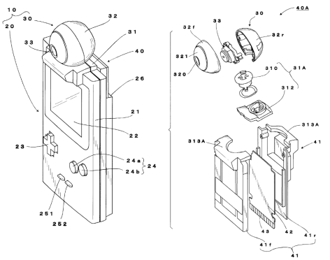
So GameBoy Camera was a pretty awesome toy in the late 90’s. With GB camera you could take pics and check them without waiting for any chemical process. There is a menu for editing the photos with endless options, and another one to make funny animations. You can even rotate the lens to make selfies!

I still keep two GameBboy Camera cartridgse but unfortunately I lost all the pictures I took when I was a kid. I don’t understand why Nintendo never thought on selling a software to save the images into a computer. The best you could do was to buy a Nintendo Printer, but It was really expensive and It never got popular in my country. When internet arrived, I bought a MadCatz cable to transfer images to the PC. But I have to say that the software was very awful, and the interface need a LPT port therefore nowadays It’s useless. So I have always being looking for an alternative.
On google you can find some tutorials from people that uses different hardware and software, but most of the times it is not easy to find the hardware and the code is not shared. So I started playing with my fancy new arduino board and that’s the result.
It was the first (and last time) I used arduino. Previously I only used PIC microcontrollers (16f and 18f). I have to say that arduino compiler is not as friendly as I thought. Maybe I should read a little more about it. And for sure the arduino IDE is very poor (but enough), but possibly it would get better on eclipse. Arduino is very limited but the key point is the price, 13 $ for an Arduino Uno shipping included. It’s a very impressive price. It deserves a chance. (If you’re not familiar with it, Arduino consists of an open-source hardware board designed around an 8-bit Atmel AVR microcontroller and IDE toolset).
The propose of this project was to copy same idea as MadCadz cable: to use the communication port between Game Boy and Game Boy Printer to get the image data without losing any bit. The first I discover on GameBoy Dev’rs was the pin out. Then I just took the oscilloscope and started taking notes of everything. Here you can find a few:
At first sight, it doesn’t look so difficult: It seems like a regular SPI bus: f(SCK) = 8.199 kHz, Vmax = 5.00 V.
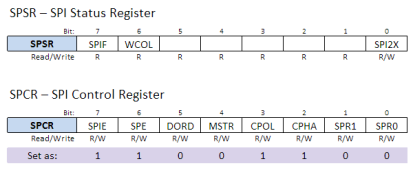
On the second screen image you can see the information needed for the bus setup, Arduino SPI – slave mode: CPOL = 1 and CPHA = 1, that correspond to SPI mode 3.
Below I write the basic code to run SPI as slave for GB camera and put the data to Serial bus. It was the most difficult part of the project, I think that when you start coding with arduino is not easy to understand how to use all ATMEL periferics. To write a byte to SPI you just have to write it in SPDR register. Maybe it is useful for your own project:
</pre>
<blockquote>
#include "pins_arduino.h"

// Buffer to put incoming data (from GB):
byte buf [100];
volatile byte bufPos;

void setup (void)
{
// Serial Debugging
Serial.begin (115200);

// SPI CONFIGURATION
// ==================

// Have to send on master in, *slave out*
pinMode(MISO, OUTPUT);
pinMode(SS, INPUT);

// Turn on SPI in slave mode
SPCR &= ~_BV(MSTR);

// Set: MSb is writen first
SPCR &= ~_BV(DORD);

// Set SPI Mode 3
SPCR |= _BV(CPOL);
SPCR |= _BV(CPHA);

// Turn on interrupts
SPCR |= _BV(SPIE);

// Enable SPI
SPCR |= _BV(SPE);

// END SPI CONFIGURATION
// ==================

// Initiate buffers
SPDR = 0;
bufPos = 0;

Serial.println("Setup done.");
} // End of setup
// SPI interrupt routine
ISR (SPI_STC_vect){

if (bufPos < 100){
buf [bufPos++] = SPDR;
} // end of room available
SPDR = 0;
} // End of interrupt service routine (ISR) SPI_STC_vect

void loop (void){
while(1){
if (bufPos > 0) {
bufPos = bufPos - 1;
Serial.println(buf [bufPos],DEC);
}
} // End of while (1)
} // End of main loop
As you can finally see the code is quite simple. You need to read Atmel datasheet to fully understand it. I decided to use Atmel register directly to write and read to SPI bus without using arduino SPI.h library because I could not understand how to use it.
These are the registers and the values I used:
You can find more information about how to connect the pins here.
With that code the only blocking point is to understand completely the communication between the Game Boy and the Printer just to emulate Printer answer and extract the image information. I use a cheap logic analyzer from dangerous prototypes to start working on the communication: Open Bench Logic Sniffer. It can work up to 100MHz waveforms on 16 channels! Here is the configuration and the result I get:
It confirms the information I got from the oscilloscope, but at the end it was not so easy to use. So finally I used Bus Pirate also from Dangerous Prototypes. To run Bus Pirate for this propose type the following commands: [m, 5, 1, 2, 1, 1, 2, (1), 3].
With this document and google help this is how I understand the communication between GameBoy and the Printer:
This table shows that GB always starts the communication with 0x88h and 0x33h bytes. After GB sends the command code [0x01h: to intialize, 0x02h: to print, 0x04h: for sending data and 0x0Fh: for Inquiry] and so on. So, at the end, all that Arduino has to do is to send acknowledgement code (0x81h or 0x88h) and status code (0x00h) after checksum bytes.
The data format is as follows:
Each image corresponds to a page. Each page consists on 9 brands. And Each brand consists on 40 tiles. GB sends a data command for each brand (640bytes).
The brand structure is not so simple, but it may help:
Putting all the bits in the correct order the result should be something like that:
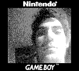
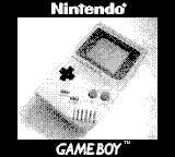
And that’s the result:
You can find all code here: https://github.com/gism/GBcamera-ImageSaver. Probably you would like to change conf.py file.
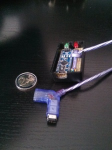
I used an Arduino nano board, but I think all the boards have the same pinout for connecting Arduino board with the game boy:
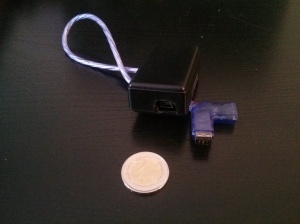
And that’s the result, an USB interface for Game boy 😀






The soil you put innto your raised garden beds iss very important, especially if you want an organic garden soil.
It can perform a great job on tthe areas that the mower can’t reach,
such as around fruiit trees, near fences, beside patios, annd many other places.
These shoulld be planted relatively shallow to help the rpot network thrive.
well nice post! found something REALLY USEFUL (what exactly about it now escapes me) while i was working on a SPI based arduino project. Also, usb gameboy! 😀
Well done. I got this to work on an Uno, but I needed to switch pins 11 and 12.
I also used a Mac and the serial communication wasn’t working until I deleted the
‘/dev/tty*’
string from line 40 of the arduinoSerial.py script.
I also had to change the “colorpanes” value from 0 to 1 on line 20 of the imgBMP.py script to get a readable bmp file.
Muchas gracias! Ahora tengo todas mis fotos de mi juventud (bueno, algunas 28) en el ordenador!
¿Como lo lograstes? yo no lo consigo
Help me please ! ” ERROR : . Unable to open serial port ” Tried Windows and Ubunty, nothing works (
Help me please ! ” ERROR : . Unable to open serial port ” Tried Windows and Ubunty, nothing works (
Nice work! I forked your code and fixed the COM port search on windows. I also updated it so that it can handle prints of any length. Many games print long prints that are not the squares like GB camera.
https://github.com/metheos/GBcamera-ImageSaver
Hey Matt,
at the moment i’m using your code. Thank you.
But i have a Problem:
Most of the time i get the Error #02 (at GameBoy) and the python script just says Waiting for Print Data…
But: Rarely some picture data is transferred to the PC, but the pixels are a mess. Sometimes the Nintento-Logo is shown up multiple times.
Can you help me please?
Check the connections, sometimes the problem that you are describing happen when the connections are not fine
Thanks for your reply.
I tried it with two different link cables and two gameboys, same problem.
Is there a way to check the connections?
Interesting. What game is it and what are you printing? I’ve only tested my code with the few games I have.
I tried it with Gameboy Camera.
Do I need a python to run scripts?
my ALIEXP arduino nano v3 need change 11 and 12 pin
I’ve tried getting this running, I believe my cable is wired correctly to my Arduino but when I run the software and attempt to print on the Game Boy this is what happens:
python.exe ./Main.py
Checking port: COM4 (3)
Arduino GameBoy ImageSaver found on: COM4 (3)
stateMachineCmd: 0 | Data: GameBoy ImageSaver v0.1: Setup done.
stateMachineCmd: 0 | Data: ?
stateMachineCmd: 0 | Data: 255
stateMachineCmd: 0 | Data: 255
stateMachineCmd: 0 | Data: 255
stateMachineCmd: 0 | Data: 255
stateMachineCmd: 0 | Data: 255
stateMachineCmd: 0 | Data: 255
stateMachineCmd: 0 | Data: 255
stateMachineCmd: 0 | Data: 255
stateMachineCmd: 0 | Data: 255
stateMachineCmd: 0 | Data: 255
The Game Boy just says “print error #02”.
Any idea what I might have done wrong?
Ah, of course, I had to switch pins 11 and 12.
Hello, amazing project, congratulations. I have a question and hopefully someone can help me: why is an oscilloscope used for this type of project? I also want to do game boy projects like this one but I don’t know if I should buy an oscilloscope. Thanks a lot
[…] + похожий метод […]
Hello, I recently got a GB Camera, and I enjoy it. I also have an Arduino UNO that has been collecting dust for a while. I am not a skilled programmer, and never got anything to work 😉
I figured I could use this to get the images of the GBC, but I can’t even figure out how to import the code into the Arduino web editor. Could anybody hint me towards a “for Dummies” description of how to get this onto the Arduino?
hello, amazing project, congratulations. I have a question and hopefully someone can help me: why is an oscilloscope used for this type of project? I also want to do game boy projects like this one but I don’t know if I should buy an oscilloscope. Thanks a lot